View all PLANS & SPECS articles
The main purpose of construction drawings (also called plans, blueprints, or working drawings) is to show what is to be built, while the written specifications focus on the materials, installation techniques, and quality standards. However, the distinction is not clear cut. Most designers put basic construction information in the drawings and use the specs to elaborate on materials, techniques, and standards to be met. Others pack their drawings with written notes that cover many of the issues commonly contained in the specs. In some cases, you’ll find the same information in both places. If there is a conflict between the specs and drawing, the specs generally override the plans, at least legally.
Scale Drawings. Nearly all construction drawings are drawn to scale. The large blueprints or “working drawings” used on the job site are typically drawn at a scale of ¼” per foot. Drawings of the whole house, or small details, may be at a different scale. At a scale of ¼” per foot, a line 1 in. long equals 4 ft., a line 4 in. long equals 16 ft., and so on. A special architectural scale ruler (photo below) makes it very easy to read dimensions on construction drawings – or to create your own scale drawings.
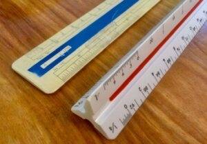
Architectural symbols. Over many years, a set of standard architectural symbols has developed for construction drawings so that anyone familiar with the building trades can understand their meaning. Different designers and draftsperson have small variations in their style of drawing, but usually their meaning is clear to anyone familiar with construction drawings. When a designer or tradesman looks at a set of drawings, every little line, arrow, squiggle, and symbol has significance. Together they provide a detailed guide to how the building goes together and what it will look like.
Level of detail. The level of detail ranges from very little in freehand “conceptual” drawings to very precise in “construction drawings” — also called “working drawings” or blueprints. In between are the simple elevations and floor plans you often see in plan books and magazines. These are drawn to scale, but contain very little detail.
The complete set of highly detailed construction drawings is used to get bids, obtain a building permit, and guide the construction process, from foundation to trim. The drawings often go through multiple revisions, so it is important to mark the finished set as the “Final Construction Drawings.” On larger projects, a later set of “As-Built” drawings may be produced to reflect changes made during the construction process.
That said, some architectural drawings are more detailed than others. For example, an architect may produce only conceptual drawings if that’s all he is hired to do. A complete set of construction drawings may still lack some of the details needed to get bids or a building permit. In that case, the contractor or building department will request additional information from you or your designer.
TYPES OF DRAWINGS
A complete set of house plans usually contains floor plans, elevations, sections and “details” that together form a detailed picture of the entire house. There is often a separate page for each major trade, including a site plan, floor plans, foundation plan, electrical plan, plumbing plan, and framing plan. In general, each drawing is either an elevation, plan, or section view, as described below:
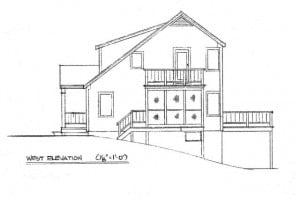
Exterior elevations:These are the sides of the building viewed looking straight at them (see below). These can be a little deceptive, since everything appears as a single, flat plane, with no clues as to depth. So, for example, a sloped roof viewed from the side looks like a flat vertical rectangle – not what you would actually see in a 3D world. Two walls or objects, offset by 10 ft. appear in the same plane. Exterior elevations give you a pretty good idea of what the house will look like on each side, but 3D perspective drawings provide a much more realistic view.
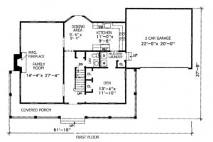
Floor plans: These are views looking straight down at the floor, showing precisely dimensioned rooms, closets, kitchens and baths, and the locations of doors, windows, stairs, and other interior elements. These may be highly detailed or simplified, as in a plan book (below).
Sections: These drawings show what you would see if you cut a slice through the building, revealing the inside of walls, floors, foundations, and other elements. Most common are elevation sections, cut vertically through the walls and floors. The location of the slice (the cutting plane) is usually indicated on the floor plan with a number and letter label in a small circle. Sections are especially useful for carpenters trying to see how the foundation, faming, insulation and other elements fit together (below).
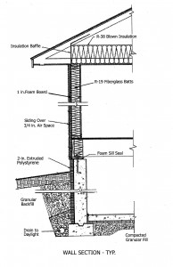
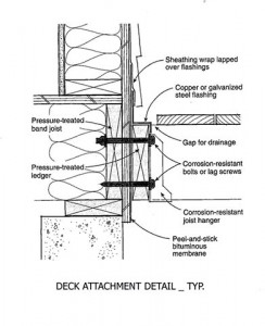
Details: These are blown-up drawings of specific elements where the designer wants to provide more detailed information. A larger scale is often be used. Details are often section drawings of the foundation, exterior walls, windows, stairs, framing, or other construction elements. The location of a detail is usually indicated on the floor plans and may be marked “TYP” to indicate that the detail is typical — repeated at similar places throughout the plan (below).
Monarch Innovation says
100% Drawings?
What are 100% construction drawings?
buildingadvisor says
Do you mean “100% complete” construction drawings?
In fact, no building plans are 100% complete down to every nail and screw. It’s not possible to specify every single detail so some decisions are made by the contractor based on the building code, industry standards, manufacturer’s instructions, and the contractor’s personal preferences.
This is especially true in the area of quality standards, where people may disagree about whether a color match is good enough or how smooth is a “smooth finish.” Highly detailed (and expensive) architectural plans do a better job of nailing down these details, but it’s never 100% clear.
It’s always good to see other work a contractor has completed to see whether you approve of the quality of their workmanship.
Cathy says
How Long to Design a House?
How long does it usually take to get a set of plans completed? Looking at a 1500 square foot chalet style home with a loft.
buildingadvisor says
There are a lot of variables here, but it sounds like yours is a pretty straightforward project of modest size.
In my experience, it usually takes from three to six months from your initial meeting with an architect/designer to a full set of construction documents (plans and specifications), that you can put out to bid.
Naturally, you should ask this question before committing to working with a designer. If they are a small office with a lot of work backed up, it may take longer than you want.
Also, you will need to decide whether you want to hire the designer for a full suite of design services or just a set of blueprints and specifications that you can use to get bids and obtain the necessary permits. Make sure you get an estimate and clear description of the design services provided before committing to a designer.
Also, make sure that the designer’s taste in design is compatible with your own. And look for someone that you feel you communicate well with. Design is a collaborative process. To work well, the process requires a lot of back and forth communication.
Best of luck with your new home!
Read more about Hiring an Architect or Designer
Sally says
Cathy, we drew ours on graph paper, then took it to a newly licensed young architect to have it made ” up to code” and structurally accurate. She was able to correct our bedroom window sizes( now latter & up to code), and also recommend a small change in the upstairs hall wall. She angled it so we had a bit larger landing, which took a small bit off the master bedroom. It turned out great.
We were thus able to help a newly opened business in our town, and have the work done quickly, because she wasn’t really backed up.
I’d do it over again.
Scott Baker, SKB Drafting & Design says
As was noted in another reply, there are a lot of variables to take into consideration.
After the initial meeting with the homeowners, much depends on the information provided, narrowing down the homeowners vision insofar as size, layout, complexity etc.
Personally I’ve had people come to me with a “stock plan” who want anywhere from slight revisions to “revised” plans that don’t even resemble the stock plan. It’s sort of a “This is basically what I’m looking for as a starting point, but this is how I really want the house to be laid out”. I had one couple that started with a 1,700 sq.ft. stock plan and ended up with a plan over 5,000 sq.ft., with a 2,500 sq.ft. shop, unrelated to the stock plan.
For something like you’ve mentioned … this could take anywhere from a couple of months to have the plans 100% completed to your satisfaction to 6 months. It just depends.
One thing to watch out for is the “fine print”, even though it may not be included in the proposal for the plans — things like added fees for consultations after a couple of initial meetings to narrow down the design. Some charge $50.00 or more per phone call or per hour for consultations beyond two. I feel 100% transparency from start to finish is paramount so that the homeowner knows without any doubts, what exactly they’re getting.
You may have one quote that is higher than others, but does not include any added charges that will, in the end, make the lower quote eventually cost much more.
Nancy Felix says
How Do I Hire An Architect?
I want to draw a building plan. How do I get an architect to help me ?
buildingadvisor says
You can hire an architect (or other professional designer) to handle everything from preliminary design to construction management, or hire them for a much more limited role such as preliminary design, which will cost you a lot less. Some designers offer a menu of prices for specific design services.
Design is a collaborative process, so it is important to find someone you feel comfortable working closely with. Good rapport and good two-way communication are critical for the process to go well. Interview a few architects or designers, and look at their portfolio, to see if you like their design style, approach to work, and price. You may wish to interview a couple of past clients.
Start your research the same way you would look for a doctor, lawyer, or other professional. Ask friends and neighbors. Local contractors can be a good source for names. You can also search online for “residential architects” or find an online directory of architects at your state’s AIA (American Institute of Architects) website.
The most efficient way to work with a designer is to initially communicate a clear idea of what you are looking for in a design. Be as specific as you can about the type and size of space you need, what issues are most important to you, and what your budget is. Ask if they can design to your budget?
Bring any sketches you have made, photos of houses you like, and clippings from magazines or pics from the Web. These will point the designer in the right direction so you don’t waste a lot of time and money spinning your wheels on designs that don’t meet your needs or tastes.
Also keep an open mind. You may find that the designer produces a creative solution that you hadn’t thought of, but that does a great job both functionally and aesthetically. So it’s good to start with some clear ideas of what you want, but to also be open to new ideas from the designer. After all, that’s the main reason you are hiring them – for their creativity in solving design problems.
Read more at these links: Architects Designers
aiman25 says
Who is Responbile if Building Does Not Match Drawings?
What happens if the construction work does not match the drawings? Who is responsible?
buildingadvisor says
The answer to your question would depend on what doesn’t match and whose fault that is. That’s not always easy to determine, since no one wants to take the blame for an error. The more common scenario is everyone pointing the finger at someone else.
It’s normal to have small differences between the contract plans and specifications and the “as-built” project. For example, a window or door is not exactly where it should be or a room ends up a little smaller. This may be caused by the need for a structural beam or a pipe or duct in the wall.
A medium-sized problem might be the wrong color or type of roofing shingles. Or a molding profile that does not quite “match existing”.
A large problem would be a building that is the wrong size, a ceiling that is substantially lower than it should be, or stairs that don’t meet the building code.
The discrepancy could be due to a mistake on the contractor’s part or the designer’s. In some cases, site conditions or the building code required an adjustment on site. Or the plans and specifications were unclear on not sufficiently detailed. It could also be due to a deliberate effort by the contractor to cut costs – for example, substituting an inferior, less expensive material for the one specified.
If the plans or specs were unclear, the contractor should have notified the owner or owner’s representative and worked out a solution, but this doesn’t always happen. Often, the contractor just interprets the unclear plans the way he prefers – or builds what he assumes the owner or architect had in mind. This can lead to conflicts when the owner or architect sees the work and says it was done incorrectly. Each made different “assumptions” but failed to communicate these.
If there is a lot of money involved and this sort of thing goes to court, the court would try to untangle who caused the problem, how to fix it, and who should pay for it. In some cases, more the one party is at fault and the cost would be shared.
In most cases, these kinds of problem are solved by negotiation between the owner, designer, and contractor. The solution might be an adjustment to the contract price, or some of the work being torn out and redone correctly. Sometimes more than one party splits the bill. If there was a big design mistake costing thousands of dollars, the architect’s Errors & Omissions insurance might cover the cost.
Best of luck in finding a workable solution!
Rachel Atkinson says
Who is Responsible if Stairs Don’t Fit?
We have a construction drawing from an architect for our basement conversion which details a staircase. However, with the work now 90% done it seems that the position and size of the staircase was not feasible from the drawing. Do we have a right to complain?
buildingadvisor says
You absolutely have a right to complain. After all, you hired two professionals, an architect and a contractor, and they made a significant mistake. It’s not reasonable to expect the homeowner to have to the expertise to discover and correct this type of mistake. That’s why you hired professionals to design and build the project.
It’s unclear from your question what the solution is and how much extra it will cost, but someone will have to absorb the extra cost. Also, you may end up with a less functional space than you planned on – an intangible that may be hard to put a price tag on.
Who is responsible for this type of mistake is not always clear and, in many cases, is shared by the architect, contractor, and owner. In an effort to reduce their liability for errors, architects often put language in their contracts indicating that “contractor is to verify all measurements on site.” They typically stamp their plans with similar language.
However, providing accurate plans in compliance with building codes and regulations is an architect’s core responsibility, assuming you hired them to prepare full construction drawings and not just for “preliminary” or “conceptual” design. For that reason, courts have generally held designers responsible for large design errors unless the construction contract specifically states that the contractor is responsible for discovering and reporting design errors.
In the best case, the architect will accept responsibility for the error, provide an alternate plan, and pay any extra cost. He may have “Errors and Omissions” insurance to cover the loss. If he does not accept responsibility, then you may need to consider sending a lawyer’s letter.
As the old saying goes, “Success has many fathers, but failure is an orphan.”
Read more on Who Pays For Architect’s Mistake? Hiring an Architect
Deborah Haylett says
Plumbing Details in Blueprints?
Hello. Can you advise on what level of detail full construction plans should have for building regulations. Specifically we would have expected details on drainage — guttering and soil waste pipes to be on the plans. Should they be?
buildingadvisor says
The level of detail in architectural plan varies, depending on the project and local regulations. All plans include the location of plumbing fixtures, but in general, do not include the location of plumbing lines (supply, drains, and vents). These are usually worked out between the plumber and general contractor to work within the framing plan and comply with local codes.
If required by local authorities, an architect can provide a mechanical plan showing the location of equipment, ductwork, and plumbing, but this is usually not required for residential projects.
A good designer takes mechanical issues into account in an effort to reduce plumbing and hvac costs, but this is usually secondary to other design issues such as a good floor plan. In a remodel with tricky mechanical issues, the design might include recommended locations for ductwork, plumbing drops, or other mechanical systems.
Also, If there is a septic system, the septic plan will typically show the elevation and location of the main building drain.
Small details like rain gutters may appear on a section drawing, but without much detail unless there is are special drainage conditions that require more detail – such as a drywell or tie-in to storm sewers. More details on issues like gutters may appear in the written specifications.
In some cases, you won’t know exactly what level of detail is required until you submit the plans for a building permit. During “plan check” the local building department may ask for additional details on some aspects of the plan. They have a lot of discretion and sometimes seem to make up the rules as they go.
Katherine says
Should Plan Fit the Site?
Hi. When drawing up a concept plan, should it be a workable plan that fits on the site? Should the site be inspected for the boundary lines to determine the layout of the building? Thanks
buildingadvisor says
You should absolutely develop a plan that fits on the site from the outset – taking into account views, sunlight and solar orientation, slope, road frontage, privacy and whatever else is important to you about the site. For example, it’s nice to locate the kitchen with some eastern exposure for morning light and to avoid the overuse of west-facing glass which can overheat a room on summer afternoons.
You can do a lot of this work yourself if you have a good design sense, but will probably need to bring in a professional designer or architect at some point to turn your ideas into a buildable plan.
Also be aware of well and septic locations, setbacks, height restrictions and other zoning regulations that might impact your design. On many smaller sites, there is often only one place where you can locate a house. If you design a house without taking all these issues into consideration, you can end up wasting a lot of time and money. If you are not sure about local zoning regulations, visit your local (town, city, county) zoning department and meet with a zoning official. Most likely, they will be happy to meet with you and offer some guidance.
If you know the approximate location of the boundaries, then that is probably enough to do a conceptual house plan. Often you can find the boundary markers with a little investigation. Otherwise a survey is a good idea. If a recent survey has been done, the records may be available through the town zoning office or county registry of deeds. The town might require you do a survey anyway when you apply for your permits to make sure that your house and septic system are located within the required setbacks.
Best of luck with your new home!
See also: Site Planning Basics Siting a House
Tom says
Resolving Conflicts in Plans
Can someone please tell me what should take precedence: a typical section detail or the notes?
Scenario: Foundation drawing states two different types of reinforcement for the same foundation, one being on the notes and the other being on the typical section detail. One would ‘assume’ that a typical detail is less site specific than the notes… Thanks
buildingadvisor says
Good question, and a tricky one.
There is no widely accepted principle for how to solve these contradictions. Many AIA contracts state that the contractor should submit any such conflicts to the project architect for interpretation.
It’s best if the issue of conflicts in the plans is addressed in the contract’s “general conditions”.
Some contracts state that one or the other (plans, specifications, written dimensions vs. scale drawings) takes precedence in the event of a conflict. Some contracts state that the document that requires the greater (more expensive) work will prevail. The contractor might be inclined to choose the least expensive interpretation.
Many contracts do not address this issue so it must be resolved by negotiation or, in the worse cases, litigation. Assuming the project is not yet built, it’s best to have the designer resolve the conflict before proceeding. While your assumption may make a lot of sense, not everyone would agree.
In my experience, misunderstandings based on assumptions and poor communication are biggest cause of construction disputes. It’s never a good idea make assumptions on a construction project. Always get it in writing and make sure everyone is on the same page before proceeding.
As the old saying goes, ASSUME stands for “You make an ass out of you and me.”
John says
Typical Loads for Foundation Plan
We have a similar question. On our Foundation Plan, there are some statements about “typical roof” and “typical floor”. Will these be taken as “required” by the city inspector? Or will they take it as a general guideline? Thank you!
buildingadvisor says
These notes probably refer to the typical roof and floor loads (live load and dead load) that need to be supported by the foundation.
Standard roof loads and floor loads are specified in the building code depending on the building use and climate (snow loads on roofs). They are calculated by the square footage of floor and roof area.
Unless there is something unusual in your plans that requires an engineer’s stamp, the city inspector will assume standard loading, which has a large safety factory built in. The loading will determine the foundation details such as wall thickness, footing size, and steel reinforcement required.
If you’re still unsure, ask the architect, contractor, or whoever supplied the foundation plan that you are using.
donald Allen says
How Many Plan Sets Required?
How many sets of drawings are needed in designing and building a house?
buildingadvisor says
The number of plan sets required depends on a number of factors. For example, is there a bank involved? An insurance company? Is it a complex plan that needs special approvals, engineering or consulting work, etc.? Also, you may need more plan sets in California than a small town in the Midwest, where life and building permits are simpler.
That said, eight sets is pretty typical – four for the contractor and subs, two for permitting, one for the mortgage lender, and one for good luck. FYI: I just applied for a “special permit” for a small non-conforming addition in a small town, and the Zoning Board of Appeals required 13 sets of plans (just elevations and floorplans), but since I drew them, I did not have to pay extra for the additional plan sets.
Best of luck with your new home!
Anonymous says
Where To Find Code Information
I have a question about the understanding of construction drawings. Where should I look for information building codes, and especially about reinforcement?
buildingadvisor says
Professionally prepared construction drawings should be in compliance with local codes, but it’s no guarantee. Getting a building permit based on the drawings and specs is also not a guarantee of code compliance. Many larger towns and cities have a formal “plan review” process to inspect building plans for code compliance. Periodic inspections during construction also help ensure that the building complies with code. However, at the end of the day, it’s the owner’s legal responsibility that construction be up to code. Some of that responsibility can be contractually shared with with the architect/designer and contractor, depending on the specific contract language and state law.
As for structural reinforcement — of concrete work, walls, roofs, etc., this should be clearly specified on the plans and it’s the sort of thing that would typically get picked up during plan check. If there’s anything unusual structurally, the building department might required an engineer’s stamp on the plan. If you’re not sure about a structural detail, for example, the size of a major support beam, it’s always a good idea to run it by a local structural engineer. The fee for an hour of the time is worth the peace of mind.